As theories go, quantum mechanics has certainly been successful. Despite its many counter-intuitive predictions, it has provided an accurate description of the atomic world for more than 80 years. It has also been an essential tool for designing today's computer chips and hard-disk drives, as well as the lasers used in the fibre-optic communications of the Internet. Now, however, the ability to manipulate the quantum states of individual subatomic particles is allowing us to exploit the strange properties of quantum theory much more directly in information technology.
We are used to thinking of information as being abstract, but in fact all information requires a physical medium for its processing, storage and communication. The basic unit of information - a bit that is either "0" or "1" - can be represented physically by, for example, the current in a circuit or light in an optical fibre. As information is represented by ever smaller physical systems, quantum effects become increasingly important. The ultimate limit comes when bits are represented by the quantum state of a single particle, such as the polarization of a photon.
Applied to information, quantum theory throws up some very odd predictions. These are not only interesting as a test of quantum mechanics, but can also bring us practical applications that are simply impossible with "classical" information technology.
QKD - Quantum Key Distribution
Overview of Classical Cryptography
Cryptography is a vital part of today's computer and communication networks, protecting everything from business e-mails to bank transactions and Internet shopping. Information is generally kept secret using a mathematical formula called an encryption algorithm, together with a secret "key" that the sender uses to scramble a message into a form that cannot be understood by an eavesdropper. The recipient then uses the same key - typically a long binary number - with a decryption algorithm to read the message.
Encryption usually involves one or more secret keys—numbers used in some mathematical operation to protect the sensitive information. For example, suppose the message to be sent is the number 4, the key is the number 3, and the encryption scheme is simple multiplication. Then the encrypted message is 12 (because 4 x 3 = 12). The receiver would divide the transmitted number, 12, by the key, 3, to recover the original number, 4. In this example, the procedure (or algorithm) to generate the encrypted message from the message sent was too simple. There are a finite number of multiples that we can search that will generate 12,so we could have easily cracked the encryption.
Ideally, you want the key to be a number which has the least number of divisible elements, which is a prime number, since our key was 3 this is a candidate. This key is small, but remember even the most powerful computers can't have infinitely large keys. For our message we must pass it through an algorithm in such a way so that we get he most use out of our key. In another example, imagine the message sent was 50, the algorithm is a one-way function that divides the message by 10, and adds 4 to this new number generating 9. We can now encrypt this message with our key, generating 9 x 3 = 27.
Our encrypted message is 27. If a person had intercepted the 27 as the message, without the algorithm or the key they would be at a loss to get 50 by mathematical guesswork alone.
Algorithms can be kept in the public domain, hence in a more realistic application, the secret key would have to be hundreds of digits long to be used in an algorithm effectively.

There are 2 broad classes of algorithm – symmetric and asymmetric. Symmetric algorithms use the same key for both encryption and decryption. Asymmetric algorithms, such as public/private key cryptography use one key for encryption and a different, though mathematically related key for decryption.
This sounds somewhat counter-intuitive. So too does the idea that keeping algorithms in the public domain still maintains secrecy. Nevertheless, In cryptography it’s not the algorithm that is needed to be kept secret. The algorithm should be designed in such a way that if it is discovered, unless the hacker has the key, Key secrecy is what’s important. Its even fair to say that if you know the algorithm inside and out, such that , you know what mathematics was used and you can reverse engineer the procedure done on the ciphertext itself, a good encryption algorithm will still keep the plaintext data secret by virtue of key security. A lock is only as good as its key in this field, a somewhat counter-intuitive notion indeed.
Almost the entirety of public/private key cryptography (used by protocols such as SSL/TLS) is based on the notion that there is no pattern to a series of prime numbers, other than that they are prime.
There is a possibility that somebody has already come up with a prime-prediction algorithm. It would certainly be in their interest to keep it secret!
The encryption algorithm has 2 inputs – plaintext and the key. It has one output, ciphertext.
If decrypting data, 2 inputs: ciphertext and the key. It has one output, plaintext.
such that the key is a prime number, only dvionly much more sophisticated than simple multiplication. Either way, without the key, you can't unlock the information.
Ideally, you want the key to be a number which has the least number of divisible elements, which is a prime number, since our key was 3 this is a candidate. This key is small, but remember even the most powerful computers can't have infinitely large keys. For our message we must pass it through an algorithm in such a way so that we get he most use out of our key. In another example, imagine the message sent was 50, the algorithm is a one-way function that divides the message by 10, and adds 4 to this new number generating 9. We can now encrypt this message with our key, generating 9 x 3 = 27.
Our encrypted message is 27. If a person had intercepted the 27 as the message, without the algorithm or the key they would be at a loss to get 50 by mathematical guesswork alone.
Algorithms can be kept in the public domain, hence in a more realistic application, the secret key would have to be hundreds of digits long to be used in an algorithm effectively.
There are 2 broad classes of algorithm – symmetric and asymmetric. Symmetric algorithms use the same key for both encryption and decryption. Asymmetric algorithms, such as public/private key cryptography use one key for encryption and a different, though mathematically related key for decryption.
This sounds somewhat counter-intuitive. So too does the idea that keeping algorithms in the public domain still maintains secrecy. Nevertheless, In cryptography it’s not the algorithm that is needed to be kept secret. The algorithm should be designed in such a way that if it is discovered, unless the hacker has the key, Key secrecy is what’s important. Its even fair to say that if you know the algorithm inside and out, such that , you know what mathematics was used and you can reverse engineer the procedure done on the ciphertext itself, a good encryption algorithm will still keep the plaintext data secret by virtue of key security. A lock is only as good as its key in this field, a somewhat counter-intuitive notion indeed.
Almost the entirety of public/private key cryptography (used by protocols such as SSL/TLS) is based on the notion that there is no pattern to a series of prime numbers, other than that they are prime.
There is a possibility that somebody has already come up with a prime-prediction algorithm. It would certainly be in their interest to keep it secret!
The encryption algorithm has 2 inputs – plaintext and the key. It has one output, ciphertext.
If decrypting data, 2 inputs: ciphertext and the key. It has one output, plaintext.
such that the key is a prime number, only dvionly much more sophisticated than simple multiplication. Either way, without the key, you can't unlock the information.
One Way Functions
Mathematical functions where it is difficult (or impossible) to get back to the source values, knowing only the output values, are known as one-way functions. There are many, but modular arithmetic gives us a method that is used extensively in cryptography.
A simple example is where, on a 12 hour clock face, you add 5 hours to 9am. The answer is 2 pm. Or written down we could say:
9+5=2
Because this is an example of modular arithmetic where the modulus is 12, we’d actually write:
9+5=2(mod12)
Let’s take a simple function:
3x where x=2
This is a function for turning 2 in to 9, because it’s the same as 3 * 3, which equals 9. There is a direct relationship between the magnitude of x and the magnitude of the function result. Using modular arithmetic can give the function a great property – unpredictability and/or randomness
| x | 1 | 2 | 3 | 4 | 5 | 6 |
| 3x | 3 | 9 | 27 | 81 | 243 | 729 |
| 3x(mod7) | 3 | 2 | 6 | 4 | 5 | 1 |
Many computer programs, such as the computer desktop for example, used password in Window stored as a one way function – albeit one that is considerably more complex than what you’ve just seen.
Classical Key Distribution
The problem with encrypting/decrypting data by symmetric means is that you have to somehow get the decryption key safely to your partner. This makes it possible to be intercepted if transmitted over a public channel, such as the internet. It’s the modern equivalent of an age-old problem that generals have had of communicating with their officers in the field for centuries. If the messenger who has the key is captured, all your communication can be decrypted, whether or not subsequent messengers know the key.
Essentially, using the one-way function alone in encryption protocols requires no authentication, so either side could be be spoofed by an active wiretapper. This is called the key distribution problem.
3 mathematicians came up with an answer to this problem: Diffie, Hellman and Merkle. They do an exchange of data which can be intercepted by anybody but which allows both sender and receiver to generate the same key but doesn’t allow the interceptor to generate the key.
The Diffie-Hellman Key Exchange allows two principals to agree on a shared key even though they exchange messages in public.
Using modular arithmetic it is possible to derive an algorithm that demonstrates how to perform the exchange between Alice and Bob.
The protocol can easily be extended into one that does also implement the necessary authentication.
The first step is to choose a large prime number p (around 512 bits). The second is to choose an integer g where g < p (with some other technical restrictions.) The protocol works as follows:
At this point, A can compute:
(TB)SA
= (gSB mod p)SA
= (gSB)SA mod p
= ((gSBSA) mod p).
Similarly B can compute :
(TA)SB
= (gSA mod p)SB
= (gSA)SB mod p
= ((gSASB) mod p).
Therefore, ((gSASB) mod p) = ((gSBSA) mod p) is the final shared key.

Follow the steps 1 through 4. In the last step both Alice and Bob have the same key: 9. From this point on they can use 9 as their universal encryption and decryption key.
A wiretapper can see all the messages that are sent, but can't do anything without having a fast way to compute logs in finite fields, which is assumed to be hard. One problem with Diffie-Hellman is that it does not generalize to send arbitrary messages.
Physical Analogy for Diffie-Hellman Key Exchange
We can use a physical analogy to better understand the principles underlining Diffie-Hellman key exchange. Consider the following:
We have two principals, A and B, each with a 3-liter paint pot that contains 1-liter of yellow paint. We will use E to denote a passive wiretapper. We can assume that mixed paint cannot be deconstructed into original colors.
A adds to her 1 liter of yellow paint a secret color SA. B also adds to his 1 liter of yellow paint a secret color SB.
A and B swap pots. E is able to observe the 2, 2-liter mixtures be exchanged, but E cannot deduce what color was added to either mixture, E can only deduce the relative color balance in the combined 4 liter mixture: 2 * yellow + SA + SB (Y:Y:SA:SB).
A adds SA to B's pot. The result (Y:SA:SB) is the key. B adds SB to A's pot. The result (Y:SB:SA) is the key.
Notice: A and B have computed the same key, but E gets a different one.
Public Key Cryptography
In public key cryptography, some keys are known to everyone, so it would seem that the key distribution problem vanishes. The approach was first published in the open literature in 1975. (Recently declassified documents in Great Britain suggest that public key cryptography was known there before 1975.)
The basic idea of a public key cryptosystem is to have two keys: a private (secret) key and a public key. Anyone can know the public key. Plaintext to a principal B is encrypted using B's public key. B decrypts the enciphered text using its private key. As long as B is the only one who knows the private key, then only B can decrypt messages encrypted under B's public key.
Some public key cryptography schemes also allow plaintext to be run through the decryption algorithm (using the private key). What is produced is referred to as signed text and it can be "deciphered" using the public key. Only the possessor of a private key can create text that is decipherable using the public key. The functionality of signed text cannot be replicated using secret key/symmetric cryptography.
Public key cryptography is usually much slower than secret key cryptography, so it is rarely used to encrypt an entire message. Typically a message is encrypted using shared key cryptography (with a secret key). That secret key is then encrypted using public key cryptography, and the encrypted message and key are sent. This is known as hybrid encryption. This method can allow for complex structures in implementing our secrecy requirements (see Figure below) : e.g. "message is readable by A,B,C,D".

History of Public Key Cryptography
(United States)
- 1975: Diffie imagines asymmetric cryptography (Diffie + Hellman)
- 1976: Diffie-Hellman key exchange
- April 1977: RSA (Rivest, Shamir, Adelman)
(United Kingdom)
- 1969: Government Communications Headquarters (GCHQ) - succesor to Bletchly Park - asks James Ellis to look into the key distribution problem. Ellis recalls a Bell Labs report about adding noise to a signal, transmitting it, and then removing the noise.
- 1973: Clifford Cocks (recent Cambridge Math Ph.D) joins GCHQ. He hears about Ellis idea and searches for a suitable function, and he thinks of RSA. GCHQ now could do public key encryption.
- January 1974: Malcolm Williamson, in an effort to try to break Cock's work, discovers Diffie-Hellman.
Uses of Public-Key Cryptography
Uses of public key cryptography include secrecy, authentication, and digital signatures.
Secrecy is obtained when principal A encrypts a message m using B's public key. Thereafter, the only way to decrypt m is to know the private key of B. (see Figure below)

In secret key cryptography, doing authentication requires having a different key for each pair of principals; in public key cryptography, each principal needs to know just its own private key. An example of a public-key authentication protocol is:

A hash is a function that digests information. It takes a message as input and outputs a short bit string (say, 128 bits). An example of a 1-bit hash would be a function that returns the parity of the message. Think of a hash as a succint summary of a message that has four properties:
- It is computationally infeasible to determine the input message m based on the digest of that message hash(m), which means the digest must convey no information about the original message.
- It is infeasible to find any message with a given digest value, which means we can't attack by replacing a message m1 with another message m2 with the same hash value.
- It is infeasible to find 2 messages with a given hash. If we don't have this property, then it is possible a person could sign a message, then the signature could be cut and pasted on to another message with the same hash.
- And finally, changing even 1-bit of the input gets completely different output, so that syntactically similar messages generate very different outputs and it is not likely that two bit-strings with the same hash value could be mistaken for each other.
These properties make a message-text substitution attack difficult given a hash. Specifically, suppose that message m is sent along with a signed hash value for m. The properties of the hash function would make it difficult for an attacker to substitute another meaningful message that has the same hash value as the original.
We can easily have multiple signatures (see Figure 1 below), as well as build up a chain of signatures which establishes a valid history (see Figure 2 below). This chaining of signatures can be used to prove such a claim as "Alice had signed the message when I got it.".


Examples of Public-Key Cryptosystems
We will now examine a few examples of public key cryptography systems.
Merkle's Puzzles
Merkle's Puzzles was one of the first public key cryptographic systems to be described. It allows A and B to agree on a secret key. Principal A invents a million keys and a million puzzles, where each puzzle encodes a different one of the keys. Each puzzle is assumed to take at least two minutes to solve and fit into 96 bits. A sends these puzzles to B. B then picks a puzzle at random and solves it. B encrypts a pre-arranged string (say 0000) with the key from the puzzle it solved. B sends this encrypted string back to A. A trys each of the million keys on the message it receives from B. The one that decrypts the message and obtains the pre-arranged string is the secret key that A will use henceforth to communicate with B.
A wiretapper C could steal the million puzzles. However, C would need to crack all million of the puzzles in order to discover the secret key. (If the wiretapper didn't know the pre-arranged string, then it can't even use a known-plaintext attack.) Since cracking each puzzle requires at least 2 minutes, the wiretapper would need on average 330 days to find the key.
Certification Authorities (Public Key Infrastructure)
It would seem that an advantage to public key cryptography is that a KDC is no longer necessary. However, how can one principal learn the public key another? How does one principal know they have the right public key and haven't been spoofed by an intruder? It turns out that some sort of server is still needed to certify which public keys belong to whom.
A certification authority (CA) is a trusted server that generates certificates of the form {name, public key}CA where CA is the certification authority's signature (private) key. All hosts are preconfigured with the certification authority's public key, therefore any host can check the signature on these certificates. Note that a CA is more attractive than a KDC because a CA it doesn't need to be on-line. Certificates can be stored anyplace and forwarded anywhere as they are needed.
Asymmetric Key Encryption
We use one key to encrypt, and a related key to decrypt data. You can actually swop the keys round. But the point is you don’t have one key. This gets round the key distribution problem. There’s a great way of describing the difference between symmetric and asymmetric key encryption. It involves the use of a box to put messages in and we have to assume the box, its clasps and the padlock used to lock it are impossible to penetrate.
Symmetric Key: You send a messenger out with a copy of the key. He gets it to your recipient who lives 10 miles away. On the way he stops at a pub and has his pocket picked. The key is whisked off to a locksmith who copies it and it is then secreted back in to the messenger’s pocket.
Some time later you send a messenger with the box containing your message. You are confident that your recipient is the only one who can read the message because the original messenger returned and reported nothing unusual about the key. The second messenger stops at the same pub. He is pick-pocketed. The copy key is used to unlock the box and read the message. The box with its message intact is secreted back in to the messenger’s pocket. You and your recipient have no idea that your communication has been compromised. There is no secrecy…
Asymmetric Key: Your recipient has a padlock and key. He keeps the key in a private place about his person. Let’s therefore call it a private key. He puts the padlock in to the box, but leaves it unlocked. He doesn’t mind if anybody sees the padlock. It’s publicly viewable. Even though it’s not really a key, let’s call it a public key. He sends a messenger to you with the box. The messenger stops at the pub and is pick pocketed. All the snoopers see is an open padlock. They secretly return the box. The messenger arrives at your door. You take the padlock out of the box and put your message in to it. You use the open padlock to lock the box, snapping it shut and you send the messenger on his way. He again stops at the pub and is pick-pocketed. They find only a padlocked box. No key. They have no way of getting in to the box. They secretly return the box to the messenger’s pocket. The messenger gets to your recipient, who use the key he secreted in a private place about his person (the private key) and uses it to unlock the padlock and read the message. Secrecy is maintained.
You can see the process is a bit more complicated for asymmetric key than for symmetric key, so it’s not something you’d want to do often. So what is often done is that instead of putting a message in the box and padlocking it, a symmetric key is put in the box and padlocked. That way, you solve the key distribution problem. That’s what happens with computer cryptography mostly. Public/private key cryptography is used to transport a symmetric key that is used for message exchanges. One reason for doing this is that asymmetric key crypto, or public/private key crypto, as it is known, is expensive, in terms of computing power, whereas symmetric key crypto is much more lightweight. When you see that a web site uses 256 bit encryption, they are talking about the symmetric key that is used after the public/private key crypto was used to transport the symmetric key from sender to receiver. Often the key lengths for public/private key cryptography is 2048 bits. You may have found yourself confused when setting up IIS with 256 bit SSL encryption and seeing keys of 1024 or 2048 bits. This is why – it’s the difference between what’s called the session key and the public/private keys.

Although the diagram above explains how 2 keys are used, where does all this public and private key malarkey come in to play?
Let’s take the example of an ecommerce web server that wants to provide SSL support so you can send your credit card details securely over the Internet. Look at the public and private keys in the following diagram.
The public and private keys are held on the ecommerce web server. The private key is heavily protected in the keystore. Many organisations will go as far as to have a special tamper-proof hardware device to protect their private keys. The public key doesn’t need to be protected because it’s, well, public. You could have daily printouts of it in the newspapers and have it broadcast every hour, on the hour, on the radio. The idea is that it doesn’t matter who sees it.

The website generates the public and private keys. They have to be generated as a key-pair because they are mathematically related to each other. You retrieve the public key from the website and use it as your encryption key. You’re not just going to send your credit card information across the Internet yet. You’re actually going to generate a symmetric key and that is going to become the plain-text input data to the asymmetric encryption algorithm. The cipher-text will traverse the Internet and the ecommerce site will now use its private key to decrypt the data. The resulting output plain-text will be the symmetric key you sent. Now that both you and the ecommerce site have a symmetric key that was transported secretly, you can encrypt all the data you exchange. This is what happens with a URL that starts https://.
There are still a couple of problems to solve here, but let’s put them on to the back-burner for a little while. We need to understand digital signatures and certificates for those problems. In the meantime let’s have a peek at the mathematics inside the public/private key algorithm. There is an interesting little story-ette around this algorithm. A researcher at the UK’s GCHQ called Clifford Cocks invented the algorithm in 1973. However, working for GCHQ, his work was secret, so he couldn’t tell anybody.
About 3 years later, 3 mathematicians, Ron Rivest, Adi Shamir and Leonard Adelman also invented it. They went on to create the security company RSA (which stands for Rivest, Shamir and Adelman). It is said the RSA algorithm is the most widely used piece of software in the world.
About 3 years later, 3 mathematicians, Ron Rivest, Adi Shamir and Leonard Adelman also invented it. They went on to create the security company RSA (which stands for Rivest, Shamir and Adelman). It is said the RSA algorithm is the most widely used piece of software in the world.
RSA Algorithm
RSA is usually used to encrypt a private key and then send that with along with a message encrypted by the private key. It uses a variable key length (usually 512 bits) and a variable block size that is not greater than the key length. RSA works as follows:
- Choose two large primes (say, 256 bits each) p and q. These must be kept secret.
- Compute n = p*q. The number n is not secret. This systems works under the assumption that factoring n is computationally intractable.
- Chose e such that e is relatively prime to (has no common factors other than 1 with) (p-1)*(q-1). The number e is usually chosen to be small. 3 and 64437 are popular.
- The public key is the pair (e, n). Note that e doesn't have to be secret. The private key is (d, n) where d is the multiplicative inverse of e mod (p-1)(q-1).
To encrypt a message m, compute me mod n and send the result as ciphertext. To decrypt ciphertext c: m = cd mod n. RSA can also be used for digital signatures. To sign a message m: s = md mod n. To check a signature: m = se mod n.
A lot of number theory is needed to prove that this technique works. One necessary theorem is: m = (me mod n)d mod n.

First, we’ll generate the public key. We pick 2 random giant prime numbers. In this case, I’ll pick 2 small primes to keep it simple; 17 and 11. We multiply them to get 187. We then pick another prime; 7. That’s our public key – 2 numbers. Pretty simple.

Now we use the public key to generate the private key. We run it through the algorithm in the diagram above. You can see we use modular arithmetic. Obviously the numbers would be massive in real life. But here, we end up with a private key of 23. The function, 7 * d = 1(mod 160) has that look of simplicity, but it’s not like that at all. With large numbers we’d need to use the Extended Euclidean Algorithm. I have to say, my eyes glazed over and I was found staring in to the distance when I read this about it:
The extended Euclidean algorithm is particularly useful when a and b are coprime, since x is the modular multiplicative inverse of a modulo b.
Now we want to use that to encrypt a message.

To keep things simple, we’ll send a single character; “X”. ASCII for X is 88. As we are the sender, we only know the public key’s 2 values: 187 and 7, or N and e. Running 88 through the simple algorithm gives us the value 11. We send the ciphertext value 11 to the ecommerce web server.
The Web server has access to the private key, so it can decrypt the ciphertext.

The web server passes the plaintext through the algorithm shown above and gets us the original “X” that was sent. The bit that says:
Plaintext = 1123(mod 187)
OK – there’s actually a problem here. In this message, every “X” would come out in ciphertext as the value 11. We could perform a frequency analysis attack on the message. In the English language, certain letters tend to appear more frequently than others. The letters “e” and “i” for example are very common, but “x” and “z” are uncommon.
![English-slf[1]](http://blogs.msdn.com/cfs-file.ashx/__key/CommunityServer-Blogs-Components-WeblogFiles/00-00-01-40-06-metablogapi/8032.Englishslf1_5F00_6854621D.png "English-slf[1]")
There is a “signature” that could be used to find the content of a message. We therefore need to encrypt much larger blocks of data than just one byte at a time.
Digital Signatures
Asymmetric keys, as mentioned earlier can be swopped around. If you use one key for encryption, you must use the other key for decryption. This feature comes in very handy for the creation of digital signatures. You’ve heard of digitally signed documents, authenticode, digitally signed applications, digital certificates and so on.

In the diagram you can see all we’ve done is combined some plaintext in to the same “message” as its equivalent ciphertext. When it’s time to check a digital signature, we reverse the process:

To check a message, we decrypt the encrypted portion, and get back plain text. We then compare that to the plain text in the message. If the 2 sets of plain text are different, it means either:
- The plaintext in the message has been altered and that accounts for the difference.
- The ciphertext in the message has been altered and that accounts for the difference.
- They have both been altered and that accounts for the difference.
In order to have a consistent message, the attacker would need to have access to the key that was used to generate the ciphertext.
Do you remember earlier, I talked about hashes? Well, because a message might be quite large, it’s often best to generate a hash of the message and encrypt that. If it’s an MD5 hash, it means you’ll only have to encrypt 128 bytes. When you come to perform the validation of the signature, you have to take the plain text portion and generate a hash before you do the comparison. It just uses the CPU more efficiently.

In this case, the message consists of a small section of ciphertext because the string-size of the input plaintext was reduced through hashing before it was encrypted. It also includes the plaintext of the message.
Depending on the data you are looking at, you’ll often even find the keys you can use to decrypt the message in plaintext within the message body. It seems like complete madness because anybody who intercepts the message could simply modify the plaintext portion of the message and then use the included key to generate a new ciphertext equivalent. That would make the message consistent.
However, if the plaintext key included in the message is the message-issuer’s public key, then the attacker would need access to the corresponding private key, which they won’t get because it’s, well, private.
But even with this there is still a problem. How do you know the message came from the sender it purports to come from? As an attacker, I could easily generate my own key-pair. I could then create a message that says I am the issuer and use my private key to create the encrypted part of the message.
When you come to check the message you’ll know that it definitely wasn’t tampered with in transit, but how do you know you can trust the public key embedded in to the message? How do you know that it’s me that created the message. That’s where digital certificates come in to play.
Certificates
Certificates are data structures that conform to a specification: X.509. But really they are just documents that do what we just talked about. The plain text data is the public key, plus other distinguishing information like the issuer, the subject name, common name and so on. It is then hashed and the hash is encrypted using the private key of a special service called a certification authority (CA) – a service that issues certificates.
When we protect a web server with an SSL certificate, we go through a 2 stage process. generating a certificate request, and then finishing it off by receiving and installing the certificate. The request part, generates a public and private key. The public key plus the distinguishing information is sent to the CA, which then creates a digitally signed document, signed using the CA’s private key. The document conforms to X.509 certificate standards. The certificate is returned by the CA, and we install it on our web server.
Anytime anybody connects to the web server over SSL, they retrieve the certificate and perform a signature validation on it. Remember it was signed by the CA’s private key. So they have to have the CA’s public key to perform the validation. If you go in to Internet Explorer’s Internet Options and then to the Content tab, you’ll se a Certificates button. That shows you all the CAs you have certificates (and therefore public keys) for. It means if you see a certificate that was signed by a CA on a web site, in theory, the CA did a check to make sure the requester was indeed the requester before issuing the certificate. It means that you have to trust that the CA did a good job of checking the requester’s validity before issuing the certificate.
Even this creates a minor problemette – how do you know the CA’s certificate wasn’t created by an imposter of some description? Well, it can have its certificate signed by a CA higher up the food-chain than itself. Eventually you get to a CA at the top of the food chain and this is called a Root CA. Internet Explorer and all the other browsers have all the main Root CAs for the Internet built-in. These are trusted organisations. They have to be! They are so trusted, they are able to sign their own certificates.
Technorati Tags: crypto primer,crypto,cryptography primer,cryptography,encryption,decryption,asymmetric key,symmetric key,public/private key,public key infrastructure,pki,certificates,digital signatures,signatures,signing,digital certificates,x.509 certificates,planky,plankytronixx
You may from time to time play with a Visual Studio command line tool called makecert.exe. It’s a tool that creates self-signed certificates. If you are just using them for development purposes on a local machine they are probably fine. You trust yourself, presumably. Sometimes you can use self-signed certificates on Internet-facing services. For example if you upload your own self-signed certificate to a service and you are sure nobody intercepted it while you were uploading it (because you were using SSL maybe), it means you can have private conversations with the service and you can be sure the service is the service you issued the certificate to. If you just sent the naked certificate, they’d be able to encrypt messages that only you could decrypt, because you’d have the private key. It’s possible to also include the private key when you create a certificate. If you send one of these certificates to an Internet service, they can digitally sign messages they send to you with your private key. Because you are assured that you gave the private key only to the service, you can be sure the messages are genuinely coming from that service and not an imposter. You have to trust that the service do a good job of keeping your private key safe.
Of course it wouldn’t be practical if every time you wanted to buy something on the Internet, in order to create an SSL connection you had to first upload a self-signed certificate. That’s why there is a large infrastructure of CAs and Root CAs built on the Internet. This infrastrucutre is called a Public Key Infrastructure or PKI. Many organisations have their own internal PKIs.

Above: Internet Explorer’s list of Trusted Root CAs.
You can also see the chain of CAs up to that chain’s corresponding Root CA when you look at a certificate.
This shows an expired certificate that was issued to my BPOS (Office 365) account by the CA called “Microsoft Online Svcs BPOS EMEA CA1”. Its certificate was in turn issued by “Microsoft Services PCA” which had its certificate issued by “Microsoft Root Certificate Authority”. As it’s a Root CA, it appears in the Trusted Root CAs container in Internet Explorer. As you walk up the chain you have to eventually get to a point where you trust the certificate. If you don’t, you’ll get a certificate error warning and a lot of messages advising you not to continue.

I’ll write another post soon that goes through a complete SSL handshake. That's a great way to explain what’s happening in crypto.
The Necessity of Security - BB84 Quantum Cryptography Protocol
Although modern algorithms such as the Advanced Encryption Standard (AES) are very hard to break without the key, this system suffers from an obvious weakness: the key must be known to both parties. Thus the problem of confidential communication reduces to that of how to distribute these keys securely - the encrypted message itself can then safely be sent along a public channel (figure 1). A common method is to use a trusted courier to transport the key from sender to receiver.
 |
| Alice wishes to send Bob a secret message - say, a bank transaction - over a potentially insecure communication channel. To do this, Alice and Bob must share a secret key - a long binary number. Alice can then encrypt her message into "cipher text" using the key in conjunction with an encryption algorithm, such as AES. The cipher text may then be transmitted using an ordinary data channel, as it will be unintelligible to an eavesdropper, and Bob can use the key to decrypt the message. In contrast to traditional methods of key distribution, such as a trusted courier, quantum cryptography guarantees the secrecy of the key. The key can also be frequently changed, thereby reducing the risk of it being stolen or of it being deduced by crypto-analysis - statistical analysis of the cipher text. |
However, any distribution method that relies on humans is vulnerable to the key being revealed voluntarily or under coercion. In contrast, quantum cryptography, or more accurately quantum key distribution (QKD), provides an automated method for distributing secret keys using standard communication fibres. The revolutionary feature of QKD is that it is inherently secure: assuming that we study and correct for all the loopholes in the laws of quantum theory, we can prove that the key cannot be obtained by an eavesdropper without the sender and recipient's knowledge. Furthermore, QKD allows the key to be changed frequently, reducing the threat of key theft or "cryptanalysis", whereby an eavesdropper analyses patterns in the encrypted messages in order to deduce the secret key.
The first method for distributing secret keys encoded in quantum states was proposed in 1984 by theoretical physicists Charles Bennett at IBM and Gilles Brassard at the University of Montreal. In their "BB84" protocol, a bit of information is represented by the polarization state of a single photon - "0" by horizontal and "1" by vertical, for example. The sender (Alice) transmits a string of polarized single photons to the receiver (Bob) and by carrying out a series of quantum measurements and public communications they are able to establish a shared key and to test whether an eavesdropper (Eve) has intercepted any bits of this key en route.
|+> = 1/√2 (|H> + |V>)
and
|->= 1/√2 (|H> - |V>)
correspond to +45° and -45° diagonal linear polarizations of the photons.
A prominent entangled quantum state of a photon pair is the so-called singlet state, which in this notation can be written as
|Ψ-> = 1/√2 (|H1V2> - |V1H2>)
In a measurement which distinguishes horizontal and vertical polarization, this state would either lead to a result with photon 1 in horizontal and photon 2 in vertical, or with photon 1 in vertical and photon 2 in horizontal polarization: The measurement results are always opposite on both sides.

This also holds if a measurement is carried out that distinguishes ±45° diagonal polarizations, since
|Ψ->= 1/√2 (|+1-2>- |-1+2>)
both H/V and ±45° measurements, the results on both sides are anti-correlated.
In a real experiment, one would get either one of two possible outcomes on each side, for example H or V on one side, and + or - on the other side if a measurement apparatus distinguishes ±45° polarizations. For measurements on many pairs, one would get a number of events NH,+, NV,+, NH,-, and NV,- for all possible combinations. From this, one can define a correlation function
EHV,± := (NH,+ + NV,- - NH,- - NV,+) / NT,
with a total event number NT = NH,+ + NV,- + NV,- + NH,- .
This correlation function can only take values between between -1 and +1. For the singlet state and the same measurements on both sides, the anti-correlation quantitatively reads
EHV,HV = E±,± = -1.
A correlation function can not only be defined for measurements H/V or ±45°, but for an arbitrary rotation angle φ with respect to the H/V directions.
The quantitative version of the Bell inequality now makes two choices of measurement orientations on the two sides; we refer to them as a and a' on one side, and b and b' on the other side. Correlation functions corresponding to these orientations ("settings") are combined to a new quantity:
S := Ea,b - Ea',b + Ea,b' + Ea,b'
With the argument of J.S. Bell, under the assumption that there is a local realistic model with "hidden" parameters determining the measurement outcomes, this quantity is bounded - expressed by the inequality
|S| ≤ 2

Quantum physics, on the other side, allows to calculate the expectation values of these correlation functions for a given state of the photon pairs. For a choice of settings a=H/V, a'=±45°, and settings b and b' rotated by an angle φ with respect to a and a', the singlet state |Ψ-> leads to a value of S.
For some angles φ, S is out of bounds fixed by the Bell inequality

A measurement of polarization correlations for a proper relative orientation φ between the two sides should therefore probe the local realistic assumption behind the Bell inequality.
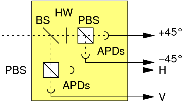 The polarization of photons can be measured by a combination of beam splitters (BS), polarizing beam splitters (PBS) and half wave plates (HW), which divert an incoming photon onto one of four avalanche photodetectors. Those devices give a discrete arrival signal for incoming photons with a probability ("quantum efficiency") of about 50%.
The BB84 protocol allows us not only to test for eavesdropping, but also to guarantee that Alice and Bob can establish a secret key even if Eve has determined some of the bits in their shared binary sequence, using a technique called "privacy amplification". Imagine, for example, that Eve knows 10% of the key bits shared by Alice and Bob. Being aware of this, Alice and Bob could then publicly agree to add together (using modular arithmetic) each adjacent pair of bits to form a new sequence of half the length. Eve may also do this, but since she will need to know both bits in a pair in order to correctly determine their sum, she will find that she now shares a much lower fraction of the new bit sequence with Alice and Bob.
So much for the principle. In practice, pulses of single photons in a given quantum state are required for BB84. Recent progress using single atoms or semiconductor quantum dots can be used to generate single photons, however most practical QKD systems use weak laser pulses of different polarization states to send the bits that make up the key.
This method has an Achilles heel: the laser will sometimes generate pulses containing two or more photons, each of which will be in the same quantum state. As a result, Eve could in principle copy one of these photons and measure it, while leaving the other photons in the pulse undisturbed, thus determining part of the key while remaining undetected. Even worse, by blocking the single-photon pulses and allowing only the multi-photon pulses to travel through to Bob, Eve could determine the entire key. (This topic of hacking the signals is continued in the last section)
This method has an Achilles heel: the laser will sometimes generate pulses containing two or more photons, each of which will be in the same quantum state. As a result, Eve could in principle copy one of these photons and measure it, while leaving the other photons in the pulse undisturbed, thus determining part of the key while remaining undetected. Even worse, by blocking the single-photon pulses and allowing only the multi-photon pulses to travel through to Bob, Eve could determine the entire key. (This topic of hacking the signals is continued in the last section)
Until true single-photon sources become available commercially, the most common defence is to strongly attenuate the laser to limit the rate of multi-photon pulses. However, this also means that many pulses contain no photons at all, reducing the rate at which the key can be transmitted. In 2003 a new trick to get round this problem was proposed by Hoi-Kwong Lo at the University of Toronto and Xiang-Bin Wang at the Quantum Computation and Information Project in Tokyo, based on earlier work by Won-Young Hwang at Northwestern University in the US.
Their idea was to intersperse the signal pulses randomly with some "decoy pulses" that are weaker on average and so very rarely contain a multi-photon pulse. If Eve attempts a pulse-splitting attack, she will therefore transmit a lower fraction of the decoy pulses to Bob than the signal pulses. Thus by monitoring the transmission of the decoy and signal pulses separately, Eve's attack can be detected. This means that stronger laser pulses may be used securely - for instance, last year at Toshiba we demonstrated a 100-fold increase in the rate that keys can be transmitted securely over a 25 km fibre. The decoy-pulse protocol has caused great excitement in the QKD community, with four independent groups having just reported experimental demonstrations of the technique.
Weak laser pulses are not the only way to carry out quantum cryptography. For example, QKD using a true single-photon source has recently been demonstrated at Stanford University, the CNRS in Orsay and Toshiba. Furthermore, in 1991 Artur Ekert, while a PhD student at the University of Oxford, described an alternative to the BB84 protocol that exploits another counterintuitive prediction of quantum mechanics: entanglement. Pairs of entangled photons have quantum states that are strongly correlated, such that measuring one photon affects the measurement of the other. If Alice and Bob each have one of the pair, they can therefore use their measurements to exchange information. This technique has been demonstrated by researchers at the University of Vienna, the Los Alamos National Laboratory and the University of Geneva, and was even used in 2004 to transfer money between Vienna City Hall and an Austrian bank. However, weak-laser QKD is the most mature approach, and the basis of the commercial QKD systems that are now coming on the market.
Practical Quantum Key Distribution - Polarization VS Phase Modulation
Information can be encoded in the quantum state of photons in several different ways. The first laboratory demonstration of QKD by Bennett and Brassard in 1989 over 30 cm of air used the polarization state of photons, which can be used to encode information via a polarization controller which can be decoded using a polarization analyzer.
All polarized light can be described in terms of an electric field vector. This vector is a representation of the light’s electric field only (the magnetic field is not considered since it is proportional to and in phase with the electric field).
For convention, this vector divided into two perpendicular components (x and y) where the third component (z) is simply the direction of wave propagation. When describing polarized light, two characteristics must be observed; First, the relative phase of the two components (x and y), and second, their relative amplitudes. These two characteristics determine the polarization of light.

There are three main types of polarized light. They are linear, circular, and elliptical polarizations.
Linear polarization describes any light where the x-y components are in phase. The relative amplitude of these two components determines the direction of polarization (measured in radians from some reference point). Linear light is most easily obtained through use of a polarizer. The output light will always be linear, independent of input polarization (except in the case of absolute extinction where no output light is observed).
Circular polarized light describes any light where the relative amplitudes are the same and there is a phase shift of exactly ninety degrees. Circular polarization is commonly described as either right-handed or left-handed. This can be visualized by imagining your thumb in the direction of propagation (z direction) and curling your fingers in the direction of the changing field. If this can be done with your right hand, it is obviously right-handed polarization, and left-handed polarization is found similarly. In reality, right-handed and left-handed circular polarizations are virtually the same. One would be concerned only in the case of mathematical convention.
The third type of polarization, Elliptical polarization, describes any polarized light where relative phase and/or amplitude are not equal (excluding the circular and linear polarization cases). Elliptical light can be described as either right handed or left handed in a similar way as circular polarization. But in this case, it is often more important to describe whether the polarization is right handed or left handed. This ellipse can be described as seen in the figure below.

Changes in both phase and relative amplitude can be monitored to characterize materials with variable birefringence. As the relative phase changes, the change can be described as an angle difference. The figure below illustrates a change in phase of the y component relative to the x component. If the relative amplitudes are the same, a full 360 degree shift may be viewed as the light changes through linear, elliptical, and circular polarizations. If the relative amplitudes are unequal, only linear and elliptical light will be observed. In either case, after a full rotation, the light will return to its original state.

The polarimetric testing process can be done manually with a set of polarizers and waveplates, such as with an apparatus below, where the looping of optical fiber can make elliptical polarization due to birefringence

These mechanical polarization controllers have fiber loops curled up in paddles, which can be oriented with respect to each other by turning corresponding handles.
This is the way a QKD controller can can choose the measurement orientation of one of the detectors, to hit a condition to violate a Bell inequality quantum entangled photon .
This can also be accomplished electronically with equipment such as the electro-optic polarization analyzer. The latter of which is much easier and more accurate but also is considerably more expensive. Both require the use of fiber-optic cables.
This is the way a QKD controller can can choose the measurement orientation of one of the detectors, to hit a condition to violate a Bell inequality quantum entangled photon .
This can also be accomplished electronically with equipment such as the electro-optic polarization analyzer. The latter of which is much easier and more accurate but also is considerably more expensive. Both require the use of fiber-optic cables.
Circular polarized light is commonly launched into the fiber in order to reduce orientation dependence of the launching end. Also, we are able to easily monitor polarization changes in comparison to the launched circular light. The circular light is obtained through use of a polarizer and a quarter-wave plate preceding the fiber launch. At the detector end of the fiber, however, orientation relative to the analyzer is significant. The analyzer will read the x and y values corresponding to horizontal and vertical orientation of the input port, respectively.
Throughout polarimetric testing it is important to promote mechanical and thermal stability as the fibers are commonly very sensitive to fluctuation. Even effects of the room’s ventilation, heating and air conditioning can be especially undesirable during testing. To increase thermal stability, a large heat sink such as a metal plate can be used. If the majority of the fiber is in thermal contact with this plate, any fluctuation will be relatively slow and uniform. The fiber may also be covered by another plate or box to protect from changes in the room’s air. Also, it is always wise to allow all equipment to warm up for at least thirty minutes before doing any type of test where high accuracy is desired.
Commercial polarization analyzers can output a display as pictured below.

Using the output display, the state of polarization can be monitored in both elliptical and spherical elliptical representations. The poincare sphere on the right is especially useful for polarization monitoring due to its ability to trace changes over time. The trace is marked by a red or blue line and will mark all polarization states recorded. The sphere monitors both relative amplitude and phase difference of the light’s polarization. Common locations are marked in the figure below.

The relative phase of the detected light is displayed as latitude on the sphere with circular polarizations at the poles. The relative amplitude (between x and y components of detected light) is displayed as longitude on the sphere. The four marked meridians correspond to horizontal, vertical, and 45 degree orientations of linear polarized light (at equator).
The polarized light is most easily recorded as Stokes parameters.
This is a vector < S0, s1, s2, s3> where:

I = total intensity
p = fractional degree of polarization (DOP)
Using the Stokes Parameters, points on the sphere can be easily recorded and used in calculations. Commercial polarization analyzers can also do several calculations automatically such as angle change between given points


The polarization controller technology is highly scalable and has been easily incorporated with microelectronics.

Scaling and expense aside, the most important obstacle from a physics point of view is that transmitting photons along an optical fibre can randomize their polarization, which is disasterous for communication. A much better approach pioneered by Paul Townsend, formerly of BT Labs in the UK, is to alter the phase of the photon.
For quantum phase estimation Suppose . The goal is to estimate
  , but the trouble is, a overall global phase is irrelevant. Somehow it has to be turned into a relative phase. Here in comes the use of the idea of Eigenvalue Kickback. Suppose instead of
  , there is a two qubit operator
  such that,


The "phase" has now landed up in the amplitude of the first photon and is measurable.
In the experimental method, weak laser pulses are injected into an interferometer by Alice. By applying different voltages to a "phase modulator" in one arm of the interferometer, Alice can encode bits as a phase difference between the two emergent pulses sent to Bob - for example with 0° representing "0" and 180° representing "1". Bob then passes the pulses through another interferometer and determines which of his two detectors, corresponding to "0" and "1", they emerge at.
For quantum phase estimation Suppose
. The goal is to estimate , but the trouble is, a overall global phase is irrelevant. Somehow it has to be turned into a relative phase. Here in comes the use of the idea of Eigenvalue Kickback. Suppose instead of , there is a two qubit operator such that,

That is we have a controlled operation. Now if first qubit is  , then
operation. Now if first qubit is , then


The "phase" has now landed up in the amplitude of the first photon and is measurable.
In the experimental method, weak laser pulses are injected into an interferometer by Alice. By applying different voltages to a "phase modulator" in one arm of the interferometer, Alice can encode bits as a phase difference between the two emergent pulses sent to Bob - for example with 0° representing "0" and 180° representing "1". Bob then passes the pulses through another interferometer and determines which of his two detectors, corresponding to "0" and "1", they emerge at.
 |
| When using optical fibres for quantum key distribution, the bit values are usually encoded in the phases of individual photons by way of an interferometer. Photons generated by Alice can travel by one of two paths through her interferometer, and similarly through Bob's apparatus. As the path (green) through the short loop of Alice's interferometer and the long loop of Bob's is almost exactly the same length as the alternative route (purple) through Alice's long loop and Bob's short loop, the paths undergo optical interference. By applying a phase delay to each of the two paths, Alice and Bob can determine in tandem the probability that a photon will exit at either of Bob's detectors - corresponding to "0" and "1". For example, if Bob sets a phase delay of 0°, Alice can cause the photon to exit at "0" or "1" by applying phase delays to her modulator of 0° or 180°, respectively. To implement the BB84 protocol in this case, Alice applies one of four possible phase delays (&min;90°, 0°, 90°, 180°) to her modulator, in which a phase of 0° or 90° represents "0" and a phase of &min;90° or 180° represents "1". Meanwhile, Bob chooses a phase of either 0° or 90° with which to make his measurement. If the difference between Alice and Bob's phases is 0° or 180° then their choices are compatible, while if it is ±90° they are incompatible and Bob will measure a random bit value. Using a classical communication channel, Bob and Alice can then post-select their compatible choices to form a shared secret key. |
For this scheme to work, we must keep the relative lengths of the interfering paths in Alice and Bob's interferometers stable to a few tens of nanometres. However, temperature changes of just a fraction of a degree are enough to upset this balance. This was a roadblock in developing phase modulated QKD and allowed the polarization modulated QKD to gain important ground in research and development.
An ingenious solution to this problem was introduced by the Geneva group in 1997, which led to the first QKD system suitable for use outside the lab. The idea is to send the laser pulses on a round trip from Bob to Alice and then back to Bob so that any changes in the relative arm lengths are cancelled out. A QKD system based on this design is currently available for about €100,000 from the University of Geneva spin-out company id Quantique.
At the Toshiba lab in Cambridge, they had also developed an alternative compensation technique that allows pulses to be sent just one way, by sending an unmodulated reference pulse along with each signal pulse. These reference pulses are used as a feedback signal to a device that physically stretches the fibre in one of the two arms of the interferometer to compensate for any temperature-induced changes. In trials with the network operator Verizon, the one-way QKD system was continuously operated for over a month without requiring any manual adjustment.
We can assess the performance of QKD systems by the rate at which secure bits can be exchanged. The faster the secure-bit rate, the more frequently the key can be changed, thus inhibiting crypto-analysis. Typical secure-bit rates for complete QKD systems are in the range 10 - 50 kbit s - 1 for a 20 km fibre link. Although this may seem low compared with the rate data are transferred in optical communications (typically 1 - 40 Gbit s - 1), it is enough for up to 200 AES encryption keys (each of which comprises 256 bits) to be sent per second - sufficient for most cryptographic applications.
The secure-bit rate that can be achieved decreases with the length of the optical link due to the scattering of photons from the fibre. For this reason, the best performance is usually achieved using photons with a wavelength of 1.55 µm, at which standard optical fibre is most transparent. Even so, when the fibres get so long that the signal rate becomes comparable to the rate of false counts in Bob's photon detector, sending a secure key is no longer possible. For the standard indium gallium arsenide (InGaAs) semiconductor detectors used to detect 1.55 µm photons, this distance is currently about 120 km. Recently the Los Alamos group has used low-noise superconducting detectors to extend secure key distribution to fibres 150 km in length. Significantly, these distances are long enough for almost all the spans found in today's fibre networks.
Although the risk of cryptanalysis is mitigated by using QKD to frequently refresh the encryption key, it is not eliminated entirely. However, this can be achieved by encrypting the message using a "one-time pad", which requires a random key that contains the same number of bits as the message. Each bit of the message is then encrypted by adding it to the corresponding bit in the key using modular arithmetic. Provided that the key distribution is unconditionally secure, as it is using QKD, and that the key is never reused, the one-time pad is completely immune to attack. The downside is the length of the key that must be exchanged. QKD bit rates are already sufficient to allow unconditionally secret voice communication using the one-time pad. In the future, higher bit rates will allow this security to be extended to other forms of data.
Today's secure-bit rates are limited by how often the InGaAs detectors can detect a photon currently once every 100 ns. Silicon-based photon detectors can operate almost 1000 times faster, but they are only sensitive to shorter-wavelength photons. As the quality of InGaAs detectors improves over the next few years, we can expect their frequency to catch up with that of silicon, leading to QKD bit rates that are orders of magnitude higher. In the interim, there are encouraging results showing that non-linear crystals may be used to shift 1.55 µm photons to shorter wavelengths for which the faster silicon detectors may be used. Higher detection rates have also been demonstrated using superconducting nanowire detectors, and recent advances with detectors based on quantum dots are also encouraging.
Towards a quantum network
One of the first real-life applications of QKD has been to secure fibre links between corporate sites in a city. Companies are increasingly using high-bandwidth optical connections between offices, data centres, server farms and disaster-recovery sites to obtain the speed and convenience of a local area network over a larger geographical area. In the early days of fibre deployment, immunity to "tapping" of sensitive data was often cited as a key advantage of fibre over copper cable. But in fact, eavesdropping on optical fibres can be accomplished by simply introducing a small bend in the fibre to extract a portion of the light; and, in the absence of quantum cryptography, it is almost impossible to detect performing such manipulations making fibre optic bugging a series threat to privacy and security.
To combat this, most companies develop so-called "link encryptors" that use the AES data encrption standard. However some companies, such as Toshiba, have already developed quantum link encryptor technology that can send data at 1 Gb/s between corporate sites, combining AES data encryption with secure key distribution using one-way QKD.
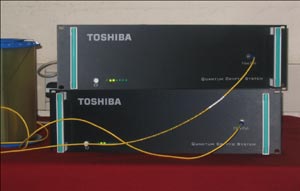 |
| Toshiba's quantum-cryptography system consists of two boxes of optics and electronics, which sit at two sites connected by optical fibre and are designed to fit inside standard communications racks. All data fed into one unit are encrypted and transmitted via the fibre to the unit at the other site, where they are decrypted. |
An important next step will be extending QKD from single point-to-point links into a "quantum network" for key distribution. Networks allow a company to connect multiple sites securely and to add new sites for an incremental cost. Moreover, they allow the range of QKD to be increased from the length of a single fibre link to any distance covered by the network, and safeguard against outages of individual links by automatically routing traffic around them.
In October 2003 BBN Technologies set up a primitive but pioneering QKD network in Cambridge, Massachusetts, linking their site with Harvard and Boston Universities. The firm showed that it was possible to direct the stream of single photons between different receiving units using an optical switch, and it also introduced the idea of "key relay" along a chain of trusted nodes. Here, each pair of adjacent nodes in the chain stores its own local key. A global key may then be sent from one end of the chain to the other, over any distance, by using the local keys and a one-time pad to encrypt each hop.
The rate of data transfer may be secure, but it has some limitations. Most obvious of which is the lack of speed, which follows from the no-cloning theorem, as QKD only can provide 1:1 connection. So the number of links will increase N(N-1)/2 as N represents the number of nodes. If a node wants to participate into the QKD network, it will cause some issues like destructing some quantum communication lines. A more sophisticated system of QKD was launched by the European SECOQC consortium in 2008 to combat this, in a collaboration of academic and industrial QKD researchers, classical cryptographers and telecoms engineers. In Vienna, It has developed the first protocols required for routing, storage and management of keys within a meshed network. In the implementation of this quantum network it allows any two users at several sites across Vienna to establish a shared key.

SECOQC network architecture can by divided by two parts. Trusted private network and quantum network consisted with QBBs(Quantum Back Bone). Private network is conventional network with end-nodes and a QBB. QBB provides quantum channel communication between QBBs. QBB consists of a number of QKD devices that are connected with other QKD devices in 1-to-1 connection.


| (a) The TREL quantum key distribution system. (b) Lower panel: secure bit rates for 24 h continuous operation for various fiber lengths: 20, 25 and 33 km. Upper panel: corresponding QBER for the various fiber lengths. (c) Secure bit rate as a function of fiber distance. Circles: experimental data derived from (b). Solid line: theoretical calculation optimized for a fiber length of 20 km. |
Meanwhile, id Quantique announced that it will install its "Vectis" link encryptor between the two centres of data-hosting company IX Europe in Zurich. In the US, MagiQ Technologies has recently developed its own encrypted link, targeted at government applications including the military, intelligence gathering and homeland security.
(a) Picture of one id Quantique device. Alice and Bob device look exactly the same.
(b) Secret key rate of system id Quantique1 over one day
From this, SECOQC can provide easier registration of new end-node in QKD network, and quick recovery from threatenings on quantum channel links. The nodes in question are situated in 19-inch racks. The photographs of the racks of nodes SIE, ERD, GUD, BRT and STP are shown below.

The principal design of the node module was carried out by the AIT Austrian Institute of Technology (formerly ARC ) in close collaboration with groups from University of Aarhus, Telecom ParisTech, University of Erlangen-Nuremberg, Bearing Point Infonova and Siemens Austria. The technical design and implementation of the module software was realized by a dedicated team from the AIT.
In what follows, we first of all give an account of the basic building blocks of the node module.
In the SECOQC approach, the main objectives of a node module are threefold:
In the SECOQC approach, the main objectives of a node module are threefold:
| 1. |
to enable the functionality of all point-to-point QKD links connected to the node, to manage the key generated over these links, and on this basis, to ensure point-to-point ITS communication connectivity to all nodes in the network associated with the node by direct QKD links;
|
| 2. |
to determine a path from the node to any arbitrary destination node in the network along a sequence of nodes connected by direct QKD links; and
|
| 3. |
to ensure an end-to-end transport of secret key material along this path using the hop-by-hop transport mechanism.
|
These three distinct types of functionalities (or services) can be grouped in network layers: a quantum point-to-point (Q3P) layer, a quantum network layer and a quantum transport layer. A schematic representation of the node module design is given below.

Design of the node module.
The interface between the QKD device(s) and the node module on one side as well as between a pair of node modules is realized by the quantum point-to-point protocol—Q3P.
The node module sets up a Q3P connection to each node associated with it by a QKD link and thus initiates Q3P links.A Q3P link realizes a context-dependent ITS communication channel. That is, depending on a header attached to the transmitted messages, it switches between different modes: (i) one-time pad encrypted and ITS authenticated communication, (ii) non-encrypted but ITS authenticated communication or (iii) non-encrypted and non-authenticated communication. To carry out this functionality each Q3P link maintains two functional entities: a key store (managing the key material), and a crypto engine (performing the crypto operations using key material from the key store), which are discussed below.
The Q3P protocol also maintains a communication line with the underlying QKD device corresponding to each Q3P link in the node. It takes care of transmitting transparently the QKD protocol messages between the peer QKD devices over the Q3P link, applying the security level, which is explicitly set in the QKD protocol communication calls. Additionally, Q3P accepts the key material that is pushed up by the QKD device and also passes over to it general node management commands.
The central element of this approach is the key store. The key store itself is organized in several levels:
- Pickup store: More then one pair of QKD devices can be attached to a single Q3P link. Every QKD device is now associated with a pickup store to which it pushes the generated keys. There are no restrictions neither in size nor in time on the devices. However, finite size considerations related to privacy amplification indicate that reasonably large chunks of key materials are to be expected. Note that the presence of key material in the pickup store has not yet been confirmed by the peer Q3P instance. Every chunk of key material has an unique identifier issued by the underlying QKD device. Using this identifier the peer key stores can perform a negotiation. A Q3P subprotocol is run, which ensures synchronous key presence on both sides. Once this protocol terminates successfully, the key material is moved to the common store.
- Common store: There is only one single common store for the Q3P link, where all keys created by all QKD devices on the very same Q3P link are collected. Here, key boundaries as present in the pickup stores are disbanded and all chunks form a homogeneous mass of key bits. The common store is persistent and will be available after system reboot.
- In/out buffers: As the communication over a Q3P link is bidirectional, pieces of key material have to be withdrawn from the common store to be dedicated for inbound or outbound communication. To prevent race conditions each key store participating on a Q3P link has one of two preselected roles—that of a master or of a slave. The master key store decides which concrete key material is to be withdrawn from the common store. The in/out buffers are crosswise interconnected. Once key material has been successfully used it is shredded and no longer available.
The key store architecture is schematically presented below:

Architecture of the key store. Two QKD devices serving the same Q3P link are connected.
These QKD networks assume that the intermediate nodes are secure, which is realistic if the network is operated by a single service provider.
In the future, however, we may be able to relax this condition using a device called a "quantum repeater". Quantum repeaters are based on the principle of quantum "teleportation", whereby a quantum state is transferred from one location to another, in principle over an arbitrary distance, using a pair of entangled particles, A and B. There is also a third photon, C, which is entangled to a quantum state but not to the other two photons. A quantum state may be represented by a group of atoms that shares a superposition between two ground states (in superposition, both ground states exist simultaneously, and there is a certain probability that the atoms are in one ground state or the other).
When physicists perform entanglement swapping by making a Bell state measurement on photons A and C, photon B also becomes immediately entangled to the quantum state, even though it has already traveled down the transmission channel.
The site where the sent photon becomes entangled with the quantum state is called a quantum repeater. Quantum repeaters, which occur throughout the transmission channel, can generate and store entanglement in order to boost the signal, with the aim of getting the entangled state to reach the other end. Entanglement can be stored by some sort of quantum memory device until, ultimately, the quantum state is “read” by being converted into another photon.
The key is that the quantum state should stay entangled with the sent photon for as long as possible, in order to maintain the quantum correlation throughout the transmission channel. Without a quantum memory, there is a small probability that quantum information can be transmitted over large distances, but the probability is exponentially dependent on the transmission length. With quantum memory, the transmission probability is only polynomially dependent on the length, greatly reducing the waiting time for a successful transmission.
Recent developments such as a semiconductor device for generating entangled photon pairs and the teleportation of quantum states between photons and atoms bring the quantum repeater closer to becoming a reality.

(A) An atomic ensemble is confined in an optical trap formed by a focused laser beam. This beam is overlapped with counter-propagating “write” and “read” beams. The resulting Stokes and anti-Stokes photons are detected, serving as a useful probe for quantum memory storage. (B) An absorption image of the optically trapped atoms. Image Credit: Thorsten Strassel.
Alternatives to using a fibre-optic network to send quantum keys over long distance may be to use free-space links to low-orbit communication satellites. In 2006 a collaboration between researchers at the universities of Vienna, Munich and Bristol implemented a free-space link over 144 km between Tenerife and La Palma to demonstrate free space, long distance QKD. Experiments with weather balloons have also been proposed which will eventually lead to more ambitious experiments with communications satellites.
Laser information transfer in general has also had ambitious project proposals, such as laser communication with Lunar Satellites which could see a quantum teleportation transfer to the moon one day, for scientific curiosity and as a tool for large baseline, high sensitivity interferometry to test aspects of General Relativity for example. .

However, if a global Quantum fiber network exists, satellite communications will most likely be classical encrypted signals, with the key transmitted over a secure quantum channel.

Therefore space-based quantum communication may be completely unnecessary but nevertheless an interesting demonstration of the technology. On the other hand quantum repeater technology, if scaled in a way comparable to modern Rubidium frequency standards and chip scale atomic clocks, could change this view entirely, leading to truly revolutionary quantum networks that could be even expanded by deep space probes carrying quantum memory devices.
Therefore space-based quantum communication may be completely unnecessary but nevertheless an interesting demonstration of the technology. On the other hand quantum repeater technology, if scaled in a way comparable to modern Rubidium frequency standards and chip scale atomic clocks, could change this view entirely, leading to truly revolutionary quantum networks that could be even expanded by deep space probes carrying quantum memory devices.
Potential for Scaling
Large-scale integrated quantum photonic technologies will require on-chip integration of identical photon sources with reconfigurable waveguide circuits. Relatively complex quantum circuits have been demonstrated already, but few studies acknowledge the pressing need to integrate photon sources and waveguide circuits together on-chip. A key step towards such large-scale quantum technologies is the integration of just two individual photon sources within a waveguide circuit, and the demonstration of high-visibility quantum interference between them.
In early 2014 Scientists and engineers from an international collaboration led by the University of Bristol have, for the first time, generated and manipulated single photons on a silicon chip, a silicon-on-insulator device that combines two four-wave mixing sources in an interferometer with a reconfigurable phase shifter.

They configured the device to create and manipulate two-colour (non-degenerate) or same-colour (degenerate) path-entangled or path-unentangled photon pairs. They observed up to 100.0 ± 0.4% visibility quantum interference on-chip, and up to 95 ± 4% off-chip. The attractiveness of the device removes the need for external photon sources, provides a path to increasing the complexity of quantum photonic circuits and is a first step towards fully integrated quantum technologies based on a silicon architecture. This is the clearest evidence yet that phase modulation is the best bet for scalable quantum optics for use in QKD.
Market for quantum cryptography
From the first laboratory demonstrations over 30 cm of air to the latest fibre-based systems operating over 100 km, QKD has certainly come a long way in the last two decades. The technology has shrunk into compact units the size of typical network equipment and is fully automated. But despite the technical progress there are significant barriers to the adoption of new cryptographic technologies.
A particular problem for QKD is selling technology based on quantum mechanics to clients who often know little about physics and are used to traditional cryptography. Another hurdle is the lack of a security certification process for the equipment. Users need reassurance not only that QKD is theoretically sound, but also that it has been securely implemented by the vendors. It is encouraging that there are several initiatives under way to establish common security standards for QKD.
As the market for QKD develops, we can expect that the price of equipment will drop significantly. Within 10 years we may see QKD used not only in corporate and government networks, but also in networks serving home users. Optical fibres are already used to deliver television, phone and Internet services to domestic users in several countries. Although current QKD systems are too expensive for such applications, they may become viable if miniaturization to microchip-scale and mass-production lead to the expected price reductions. The days when the products of the quantum-information industry serve every household may not be too distant.
Portable Quantum Cryptography Devices

Researchers at labs in Los Alamos National Laboratory, America and Bristol, UK have both been developing small scale quantum key distribution devices which utilize polarization controllers. This is a significant step and is one that warrants attention as it is the first step towards developing devices which could carry QKD technology.

The new Los Alamos hardware employs a laser together with variable-direction polarization components to establish a secret key between sender and receiver. The key could be used to encrypt (and later decrypt) a message sent by any means—over the Internet, phone, satellite, or even carrier pigeon. That is, only the key generation requires a quantum channel—photons, polarizations, and fiber optics. Once the key is established, the encrypted information can be sent by any available means, including wireless.
a new technology they call QKarD. (The capitalized letters stand for quantum key distribution.) QKarD is a small, handheld smart card that can supply quantum keys for a variety of uses. When the card is docked in its charging station with a fiber-optic network, it automatically establishes the next thousand or so keys it will need and stores them in secure memory. The card can then be undocked and carried around by its owner.
Because quantum keys must be established between a sender and receiver, and the QKarD doesn't know who the next receiver will be while it is docked, an external server is needed to manage all transmissions. This server would reside with a trusted private or government agency. A docked QKarD establishes keys between itself and this agency.
When the QKarD owner wants to send a secure transmission—for example, to transmit her credit card number to an online bookstore—she connects the QKarD to a computer or other mobile device. Her credit card number is encrypted with the next available quantum key on the QKarD, and the transmission is sent to the bookstore. The bookstore notifies the trusted agency that the transmission occurred but does not share the encrypted credit card number with that agency.
The bookstore uses QKarD technology just as the consumer does, so it has its own quantum keys already established with the same trusted agency. At the time of purchase, the agency tells the online bookstore which bits to flip (from 0 to 1 or vice versa) to transform the bookstore's next available quantum key into the same quantum key from the buyer's QKarD. In this way, a common quantum key is established between the buyer and seller with the help of the trusted agency, but without the buyer needing a fiber-optic connection at the time of the purchase.
This QKarD system is completely mobile, apart from the need to be docked from time to time to acquire quantum keys while charging. Therefore it could serve all wireless transmissions—laptop computing, cell phone calls, e-commerce, and so forth. For example, QKarD technology could be integrated into a future generation of smart phones. Every transmission from every app would be secure.
This QKarD system is completely mobile, apart from the need to be docked from time to time to acquire quantum keys while charging. Therefore it could serve all wireless transmissions—laptop computing, cell phone calls, e-commerce, and so forth. For example, QKarD technology could be integrated into a future generation of smart phones. Every transmission from every app would be secure.
Scrambled Bits
The Los Alamos team has also created a second prototype system for enhanced security and privacy. Known as quantum enabled security (QES), it is both a device and a communications protocol. It uses QKarD keys to hide data transmissions from potential eavesdroppers.
Some networks that provide fiber-optic lines to homes, for example, employ 32 wavelengths simultaneously to 32 homes. The receiving electronics system in each home is programmed to pay attention to just one particular wavelength and ignore the other 31. So everyone's data also goes into 31 other homes. But the QES system uses a secure quantum key to obscure every message in both wavelength and time. Messages are scrambled with different bits hopping among different wavelengths at different moments. Only the authorized receiver's hardware, which has the key, knows how to unscramble the hopping and pay attention to only the right wavelengths at the right moments, to pick up every 0 and 1. This is known as physical-layer security—the most robust kind—because one needs to physically select the right bits to acquire the hidden, encrypted message. While other security schemes allow eavesdroppers to record encrypted messages, eavesdroppers on a QES system can't even identify which bits contain the encrypted message.
The QES technology is limited by the distance a single photon can travel through fiber-optic cables without its polarization degrading. That distance is at least 140 kilometers (87 miles), meaning that hardware needs to be placed at stations no more than 140 kilometers apart. (It is possible to break a 280-kilometer transmission, for example, into two 140-kilometer transmissions that each have their own key.) Until such hardware is set up throughout the country or the world, QES is ideal for more localized security, such as between buildings on the same campus, industrial site, neighborhood, or metropolitan center. It is also well suited for securing information within isolated entities, such as U.S. embassies abroad or national security facilities like Los Alamos National Laboratory.
Also, as discussed earlier, the polarization control technique is limited to small scale networks due to the fact that randomization occurs to the polarization state over large distances. For large scale, phase modulation is necessary along with quantum repeater technology. In this way, using existing architecture on telecommunications, more secure financial transactions could arise; replacing debit and credit cards with mobile phone application software with access to QKD servers, at a bank or phone service provider.
Photon pairs with a strong correlation in time can not only be prepared from cascade decays in atoms, such as in single photon laser sources, but also in a nonlinear optical process called spontaneous parametric down conversion, SPDC.
In appropriate materials, photons from a strong light field can be "broken up" into pairs of photons of lower energy, as long as the total energy and, depending on the boundary conditions, the total momentum is conserved.

Entangled pair sources have seen a dramatic improvement in the last few years; light is now generated into optical fibers, and can be conveniently transported. They also help to block unwanted light wavelengths, creating a coherent entangled photon source:

Addition of compensator crystals to the polarized photon source has the overall effect of increasing the time correlation between the 2 entangled photons by several orders of magnetude.
This is a technique employed in polarization microscopy, which produces highly accurate analytical instruments that can be employed to determine the relative retardation (often symbolized by the Greek letter Γ) or optical path difference between the orthogonal wavefronts (termed ordinary and extraordinary) that are introduced into the optical system by specimen birefringence, in this case the birefringence of the BBO crystal itself. Normally this is compensated by placing the crystal in an oven, however this is energy intensive, bulky and damages the crystal in the long run.
The terms relative retardation, used extensively in polarized light microscopy, and optical path difference (Δ or OPD), are both formally defined as the relative phase shift between the orthogonal wavefronts, expressed in nanometers, according to the equation:
where t refers to the thickness of the specimen (the physical distance traversed by light waves through the specimen), n(e) is the refractive index experienced by the extraordinary wavefront, and n(o) is the refractive index experienced by the ordinary wavefront.

The terms (refractive index and thickness) on the right side of the equation are collective referred to as the specimen birefringence. From this relationship, it is obvious that specimens having differing thickness and refractive index gradients can display identical optical path differences or relative retardations. Furthermore, if either the birefringence or the thickness of a specimen is known, the other parameter can be easily determined.
Compensators are usually composed of optically anisotropic quartz, mica, and gypsum minerals ground to a precise thickness and mounted between two optical windows having flat (plane) faces, which are designed to introduce a fixed amount of retardation between the orthogonal wavefronts passing through the crystal. Needless to say, these compensators are expensive, as are quartz waveplates in general. More recently, several manufacturers have shifted to the application of a highly aligned and stretched linear organic polymer to produce anisotropic retardation plates to combat costs.The terms (refractive index and thickness) on the right side of the equation are collective referred to as the specimen birefringence. From this relationship, it is obvious that specimens having differing thickness and refractive index gradients can display identical optical path differences or relative retardations. Furthermore, if either the birefringence or the thickness of a specimen is known, the other parameter can be easily determined.
MuonRay Enterprises Quantum Entanglement Experiments - Opensource Quantum Random Number Generation for Cryptography
Interested by these developments, I took it upon myself to see if I could construct a portable quantum optics device myself, using a non-linear crystal of Beta-Barium Borate (BBO) as a parametric down-converter for 405nm laser light.

Crystal of Beta-Barium Borate (BBO) performing Spontaneous Parametric Down Conversion (SPDC) of 405nm laser light. This process can form random entangled photon pairs.
Below is a video of such an experiment performed in 2013:
Below is a video of such an experiment performed in 2013:
Both pair photons are generated at the same wavelength (810nm) or at different wavelengths.
The use of a beamspliiter creates a coherent source of entangled photons. Hence we can consider two different approaches to

(a) Detection by beamsplitter approach employs the particle nature of photons.
In this design, detection obtained this way will always be somewhat biased due to the inevitable imbalance in photon detection rates between the two detectors. photons here are from an incoherent source, i.e. starlight or lightbulb.
(b)Detection by wavefunction collapse employs wave-like nature of photons.
In this design, the photon detection rate imbalance is avoided by having a coherent, long-lasting time correlated entangled photon which will collapse into a time window defined by a measurement (provided that each measurement time window is much smaller than the photon coherence time itself).
Using entangled photons from a 405nm laser diode pump as the source with a coherence time of 1ms, while the detector is gated at 1GHz with each detection window 1000 times smaller than the coherence time. Such a large disparity in time ensures an equal detection probability between any two adjacent detection gates. By assigning a bit value ‘0’ or ‘1’ according to a detection event at an even or odd clock cycle, a bias-free random number is readily obtainable.

Figure 2. Photon count rate as a function of incident light intensity recorded for a self-differencing indium gallium arsenide single-photon APD. A maximum photon count rate of 497MHz is measured, which is very close to the value expected from a theoretical calculation (black line) assuming zero detector dead time.
To realize this scheme, it is crucial for the detector to have certain characteristics. Ideally, the detector should be operated in gated mode in order to allow unambiguous bit-value assignments. Moreover, to achieve high bit rates that are free of bias, the detector must be able to handle high photon rates and possess a negligible counting dead time.
Semiconductor avalanche photodiodes (APDs) are well suited to this task. Operated under a self-differencing mode4 that was originally devised by us for megabit-per-second (Mb/s) secure key-rate quantum key distribution,1,2an analog telecommunication APD can be converted into a high-speed single-photon detector. Using this system, we achieved a record photon count rate of ~500MHz and an ultra-short dead time of less than 2ns (see Figure 2).5

Incorporating a self-differencing APD, we have initially realized a quantum RNG with a random bit stream of 4Mb/s.3 Importantly, the quantum randomness has survived in this physical realization, and the random number outputs are intrinsically free of bias and do not require mathematical post-processing to pass random number statistical tests.
It is the first time that any quantum RNG—and perhaps any physical RNG—has not required post-processing to pass stringent randomness tests. Furthermore, by using finer photon timing, the random bit rate can be increased by over an order of magnitude to 52Mb/s with no degradation in randomness.6 Figure 3 shows a visualization of the random output from our 52Mb/s RNG.
Despite the state-of-the-art performance, the bit rate must be improved to serve demanding applications, such as high bit-rate quantum key distribution.1,2 Presently, the random bit rate is limited by the photon recording electronics, which can manage photons at only 5 million per second.
In future work, we aim to design electronics to cope with a photon rate of 1 billion per second and with such technology available, we expect to see the bit rate surpassing 100Mb/s. Using finer timing, a bit rate of multi-gigabits per second is in sight.
Silicon Avalanche Photodiodes (APDs), of the kind used in military laser rangefinders and hyperspectral CCDs, are used to detect the 810 nm photons.

For the mode where 2 photons of different frequencies are generated, 680nm for Alice and 1550nm for Bob, Silicon Single Photon Avalanche Photodiodes (Si-SPADs) have perfect properties for the 680nm photons at Alice's side.
Bob's telecom 1550nm-photon has low transmission losses in optical fibers. Bob's photon is detected by InGaAs-APDs that need to be gated as usual.
Therefore an optical trigger pulse co-propagates with each signal photon to open the detector for few nanoseconds.
The information sheet provided below is the most complete and accurate information on the number allocations and RC-5 commands available at this time. It is from a printed document from Philips dated December 1992.

The RC-5 code from Philips is possibly the most used protocol by hobbyists, probably because of the wide availability of cheap remote controls.
C5 is stream of 14 equal length bits of exactly 1.778ms per bit time.
A pulse during the first half of the clock time represents 0, a pulse in the second half of clock time represents 1. This scheme is called Manchester coding

This form of coding, converts the original data into the Manchester value by means of a clock XOR gate.
original data = clock XOR = Manchester value
0 0 0
0 1 1
1 0 1
1 1 0
Manchester encoding is a special case of binary phase-shift keying (BPSK), where the data controls the phase of a square wave carrier whose frequency is the data rate. Such a signal is easy to generate.
The bits are now represented by two phases, on the real axis, at 0° and 180°.

This is the classical 2D constellation interpretation of the bits, the qubits will be on opposite points on the 3D Bloch sphere.

Phillips itself has since moved to RC-6, probably in response to semiconductor companies in china making clones of its CMOS VCO chip technology.
Therefore, using the various protocols used in infrared communication, there is already an electronics infrastructure in existence which can be utilized to test quantum key encryption in free space with relative low cost.
The principal idea of this setup is to use the unique quantum mechanical property of “entanglement” in order to transfer the correlated measurements into a secret key.
Using a combination of our knowledge of generating entangled photons by SPDC and the Phillips RC-5 protocol, prototypes of a portable quantum entanglement device were developed.
The first prototype is a system that interfaces with a digital to analog system to send a key from a computer to the entanglement source which then sends the pairs of entangled photons which can be received via a parabolic dish which focuses the light to an infrared sensor.
The second prototype uses a fiber optic link between the emitter and receiver in a more compact circuit.
The third prototype uses a highly compact transceiver system that can send and receive quantum keys. The receiver system is also a new flexible and transparent fiber optic relay that can cover a wide area and is flat so that it can be hidden on the side of the device until deployed. such a system is particularly useful for making the technology portable via a single unit which could be designed around the perimeter of a functioning device, such as a handheld device (phone, tablet computer, ect).
Using existing detector infrastructure, a passive system performing measurements can be implemented, where all photons find their way towards their detectors without the need to control any of their properties actively. As a result, correlated measurements are generated at Alice and Bob without any input for choice of basis or bit value for individual qubits.

QKD-system using entangled photons measured at Alice and Bob. The correlated measurements from single-photon detectors are further processed and transferred to a symmetric, secure key by the QKD software. Alice, the server, uses a low-intensity, short range 680nm channel, where as Bob, the client, uses a relatively more robust telecom 1550nm channel.
For long-distance quantum fiber-communication systems it is essential to have a high flux of photon pairs generated by spontaneous parametric down conversion in the orthogonally oriented crystal geometry.
Even the best non-linear crystals have limits on their efficiency at generating pairs of entangled photons. To increase the conversion efficiency, a periodically poled nonlinear crystal with a high non-linear coefficient, such as BBO, can be used.
Periodic poling is a formation of layers with alternate orientation in a birefringent nonlinear crystal. The crystal domains are regularly spaced, with period in a multiple of the desired wavelength of operation. The structure is desired to achieve quasi-phase-matching (QPM) in the material.
Tests have shown that, with periodic poling, the crystals are up to 20 times more efficient at second-harmonic generation than crystals of the same material without periodic structure.
A compact entangled photon source can be pumped by a 405-nm-laser and its polarization is rotated to 45° for equal crystal excitation. The nonlinear ppBBO crystal is quasi-phase matched for all three wavelengths involved, 405nm, 680nm, 1550nm.

Schematic of the source of entangled photons. Within the nonlinear, periodically poled BBO crystal, single 405nm pump photons are converted to two photons at 810nm in the H and V modes, polarization entanglement is then generated.
the 810nm wavelength can be used in existing fiber optic telecom technology, and the entangled nature of the photon opens up a range of ways to test QKD in existing equipment and infrastructure.
For example, using fibre optics it is possible to interface a telecoms 1550nm signal with a Lithium Niobate Electro-Optic Modulator (EOM). This can open up the possibility of having active system for performing measurements.
If lithium niobate is exposed to an electric field, created by placing a parallel plate capacitor across the crystal, light will travel more slowly through it. The phase of the light leaving the crystal is directly proportional to the length of time it takes that light to pass through it. Therefore, the phase of the laser light exiting an EOM can be controlled by changing the electric field in the crystal.
A phase modulating EOM can also be used as an amplitude modulator by using a Mach-Zehnder interferometer. A beam splitter divides the laser light into two paths, one of which has a phase modulator as described above. The beams are then recombined. Changing the electric field on the phase modulating path will then determine whether the two beams interfere constructively or destructively at the output, and thereby control the amplitude or intensity of the exiting light. This device is called a Mach-Zehnder modulator.
As discussed earlier, phase modulation using electro-optic modulators is more robust and does not disturb the polarization state, which can become randomized in an optic fiber over short distances. Hence, by having an active system of phase modulation we can have active QKD which is relatively stable.
Therefore Alice, the server, could in principle have several clients which share the common quantum key but which are free to modulate their individual signals via phase modulation, which does not disturb the polarization state of the entangled photon.
All of this is a way to test some basic principles of QKD with scalable equipment for applications in both fiber and free space communications
Quantum Correlated Holography For Sub-Shot Noise Imaging
The first photographs of downconversion light from a Beta Barium Borate (BBO) parametric downconversion crystal were take in the Innsbruck laboratory of the Institut für Experimantalphysik by Michael Reck and Paul Kwiat [Reck 1996]. They used high-speed infrared film and a 35mm single-lens reflex camera with the lens removed. The UV-light from the pump laser and fluorescence from the crystal were held back by stacks of UV-cutoff filters.
The camera was 11cm from the crystal with the UV-pump beam (wavelength 351nm) pointing to the center of the film. Interference filters with 5nm bandwidth selected a single color. A great number of photographs were taken on Kodak high-speed BW infrared film with different exposure times. The photographs were developed for 4min using Ilford Tech HC developer by Photo Grattl, Innsbruck. The optimal contrast on the film was achieved for exposure times of 1 hour at a UV-pump power of 165mW. The entangled photon pairs from this source were used to demonstrate a violation of Bell's inequalities by over 100 standard deviations in less than 5 min [Kwiat 1995].
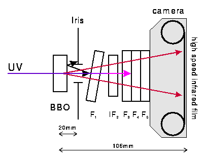
| Figure 1: Schematic of the setup used to photograph type-II downconversion: The BBO crystal is pumped by an Argon ion laser with P=200mW at 351nm . An iris diaphragm helped to reduce background and reflected light. A tilted UV cutoff filter (UV-Sky F1) is used to reduce fluorescence from the exchangeable interference filter (IF2). We used 681nm, 702nm, 725nm interference filters with 5nm full-width-half-maximum (FWHM) bandwidth. A stack of cutoff filters (UVHaze F3, UVHaze F4, O2 F5) further reduce the background light. The camera is a Pentax K2 35mm single-lens reflex camera with the lens removed. The typical exposure time for the high speed infrared film was one hour. |
| Figure 2: Transmission curves of the cut-off filters used to photograph type-II downconversion from BBO. |  |
Original Infrared Film
Figure 3: High speed infrared film exposed with light from type-II downconversion in BBO. A 681nm interference filter with 5nm bandwidth was used for this image.

Figure 4: High speed infrared film exposed with light from type-II downconversion in BBO. A 725nm interference filter with 5nm bandwidth was used for this image.

Figure 5: High speed infrared film exposed with light from type-II downconversion in BBO. A 702nm interference filter with 5nm bandwidth was used for this image. Polarization-entangled photons are observed at the intersection of the two circles.

If we exploit the properties of quantum correlation of photons in entanglement, between two light beams, one sent to a physical object and the other kept as a reference, then it will also be possible to identify conditions that would be otherwise prohibitive due to classical constraints on sensitivity.
In this synthesis it is important to note that the number of photons of the single beam fluctuates randomly, but where the number of photons in the two beams fluctuates in unison.
The possible applications of the scheme are currently still hypotheticalexperimental, but range from from the identification of a poorly reflective object flying in the sky during the day, to the revelation of the presence of pollutants weakly reflective / absorbent in the atmosphere.

Experiments on "quantum illumination" has also demonstrated for the first time a protocol based on quantum correlations that can be efficient even in the presence of a noise (in the case even predominant): this represents a significant advance since all the protocols based on the entanglement achieved so far (from the transporter to ' imaging sub shot noise, from quantum computing to quantum cryptography) are extremely sensitive to the presence of noise, the presence of which quickly erases the benefits of quantum scheme. This result contradicts the opinion then, which was rooted, that quantum protocols are all extremely sensitive to noise and therefore difficult to apply in real-world conditions.

Experimental scheme for '"imaging sub shot noise" using entangled photons from a parametric down-converter crystal. Such schemes could image objects impossible to image due to classical restraints on light reflection and transmission. Moreover, they could allow for quantum protocols to exist in the presence of environmental noise.
A proposal for testing this technology with a weather balloon and portable reflector telescope may also be a possibility with new versions of this equipment, which would be hindered if the detector or transmitter apparatus on board a weather balloon is too large. This opens up a possibility of having secure quantum communications and detection protocols in free space with fully portable infrastructure such as satellites, weather balloons or even manned and unmanned aerial vehicles.
Hacking Quantum Signals - Stress test of QKD
However, it is important to bear in mind that quantum cryptography only protects transmissions. Alices and Bobs messages can still be tricked or coerced by inherent vulnerabilities in the detection system. Hence, conventional safeguards like passwords are still important.
In practice, no quantum cryptographic system is perfect and errors will creep in owing to mundane environmental noise. Quantum physicists have calculated that as long as the mismatch between Alice's and Bob's keys is below low error threshold of ~8%, then security has not been breached.

Moreover, for certain QKD systems a hacker of quantum cryptography could disguise his interference as acceptable levels of noise, however as we have seen there are protocols being developed which can negate the effects of noise therfore the level of noise detectors will find acceptabe will always decrease. This is possible by having an arms race of sorts between the vendors of QKD equipment and people actively researching ways to make the most sensitive detectors possible which compensate noise, which is no easy task.
Alice polarizes each photon at random using either a horizontal–vertical polarizer or a polarizer with two diagonal axes. Bob detects each photon by also randomly selecting one of the two different polarizers.
If Bob happens to pick the same polarizer as Alice, then he will definitely measure the correct polarization of a given photon. Otherwise, as the Heisenberg Uncertainty Principle dictates, there is a 50% chance he will get it wrong. Once he has made all the measurements, Bob asks Alice over an open channel which polarizers she used for each photon and he only keeps the results for those measurements where he happened to pick the correct polarizer, and this series of results becomes the secret key.
Meanwhile, an eavesdropper, "Eve", who seeks to measure the polarization of the photons sent by Alice would reveal her presence because, given a long enough string of photons, the probability of her correctly guessing Alice's sequence of polarizers becomes practically zero.

When she makes incorrect measurements, she randomizes the polarization. This means that in some of the cases where Bob should make a correct measurement, he makes a wrong one. So, again speaking openly with Alice and comparing a small subset of the key, Bob realizes there is an intruder if that subset contains errors.
There is however a way to hide Eve's eavesdropping by exploiting a weakness in the single-photon detectors used in many commercially available quantum-cryptographic receivers. This involves Eve using a bright laser light to "blind" the four avalanche photodiodes that Bob uses to detect photons in each of the four different polarization states. Eve, therefore must contain a Bob', to detect the photons, and Alice', to generate a photon with the same polarization as the detected photon, where the output of Alice' must be coupled, via and optical amplifier, to the blinding laser

The laser-blinded photodiodes are no longer sensitive to single photons, but instead behave like classical detectors that generate a current proportional to the intensity of the incoming light and respond to pulses of light above a certain intensity threshold.
In the case of phase controlled QKD the spatio-temporal mismatch created by the optical amplifier could be detected by Bob by means of an interferometer, as the bit values are encoded in the phases of individual photons.
The interaction of intense laser light can lead to the re-absorption of previously generated photons, depending on the relative phase between the two. Different phase velocities lead to destructive interference due to the lack of optical momentum conservation between the photons, known as “phase mismatch”.
The interaction of intense laser light can lead to the re-absorption of previously generated photons, depending on the relative phase between the two. Different phase velocities lead to destructive interference due to the lack of optical momentum conservation between the photons, known as “phase mismatch”.

Left: Traditional concept of spatial phase mismatch.
Right: Natural extension to spatiotemporal phase mismatch by considering that dipoles radiate in space–time.

 For sufficient phase mismatch between signal paths 2 independently adjustable clock phases for Alice and Bob are generated from a calibrated delay line.
Bob's clock phase is placed in the middle of the eye to recover the data, while Alice's is swept across the delay line. The samples produced by the two clocks are then compared, by classical means, to generate eye information, which is then used to determine the best phase for data recovery. The functions of the two clocks are swapped after the data phase is updated; this ping-pong action allows an infinite delay range and thus would make an infinitely large number of ranges for a hacker to chose a phase for silent data recovery, hence negating any (known) means for attack.
Using the Quantum Random Number Generator however as an entropy source for a backup key is useful as it depends on the anti-correlations.
Any investments made by governments and corporations into this new technology will be guaranteed by the laws of physics, but only as much as we understand them.
Hopefully with more stress tests we will continue onward, improving on design and discovery and implementing this technology with the best intentions, trying to bring about a more connected, but more secure, global civilization.
Hopefully with more stress tests we will continue onward, improving on design and discovery and implementing this technology with the best intentions, trying to bring about a more connected, but more secure, global civilization.


